
GOAL-H 1c
At least 65 km/h
Achieved by sizing the output sprocket for the chosen electric motor. The gearing decides whether the bike delivers torque on a climb or top speed on the flat – we size it for this target.
Technology
This page is deliberately detailed: supervisors, the examination board and technically minded partners should be able to follow exactly what we keep, what we replace and what we develop ourselves.
Concept
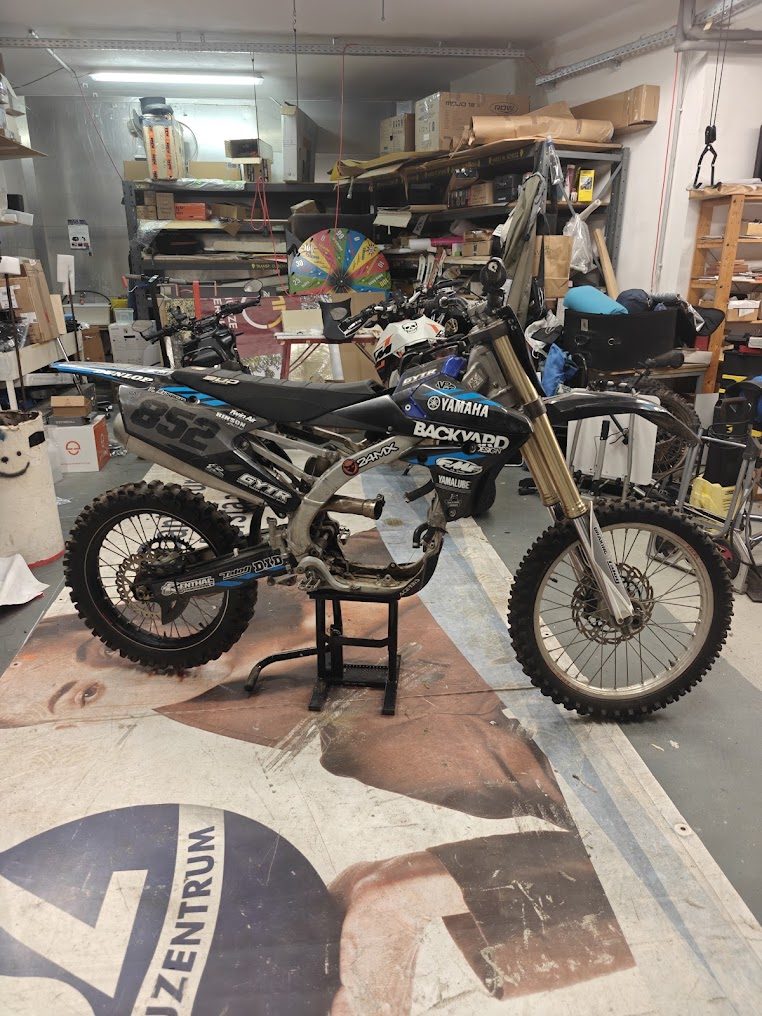
The starting point is a used 450 cc motocross bike, fully functional except for its combustion engine. That is exactly what makes it ideal: a proven chassis at the price of a broken vehicle. The bike is already in the workshop.
We remove the entire combustion engine including tank, exhaust and all related components.
We integrate an electric motor, a self-built battery pack with a battery management system and a powerful motor controller.
We keep frame, swingarm, suspension, brakes and the entire periphery. Where production engineering is already mature, developing our own would be busywork.
Targets
Two numbers drive the entire design. Everything else follows from them.
GOAL-H 1c
Achieved by sizing the output sprocket for the chosen electric motor. The gearing decides whether the bike delivers torque on a climb or top speed on the flat – we size it for this target.
GOAL-H 3a
This determines cell type, system voltage, capacity and the physical layout of the pack. At 2,500 euros the battery pack is the most expensive and by far the most demanding assembly in the project.
Assemblies
Motorcycle chassis, motor mount, CAD model of the frame, small parts and brackets plus all manufacturing and assembly elements. The choice of manufacturing methods – 3D printing or CNC – is in progress.
Electric motor, battery cells, the pack as a CAD model, the welded cell assembly, the finished pack plus wiring and safety components. Motor, cell type and BMS are currently being selected.
Microcontroller, motor control software, sensors, control logic and the fine-tuning parameters. The controller is the interface between rider input and motor controller.
Interface concept, the user interface software, a display in a self-designed handlebar housing, riding modes selectable via buttons, GPS module and wheelie module.
Motor mounts, the battery enclosure and every bracket have to fit a frame to the millimetre – a frame for which no CAD data exists. Either we model it by hand or we scan it. A precise digital model decides how often we have to remake parts, and with it our cost and our schedule.
Mechanical design
The frame is rebuilt in CAD or captured with a 3D scanner. On that basis we design the mounting elements and every bracket.
Optional goals
Two extensions we will build if the schedule allows. They are declared optional on purpose – they are not a promise.
GOAL-O 1
Software that sends live GPS data to the display and evaluates it – the basis for track logging and for analysing test rides.
GOAL-O 2
Electric motors deliver full torque from the first revolution. Wheelie control limits acceleration so the bike does not flip backwards.
Safety
A self-built battery pack holding several kilowatt hours is the point where both the examination board and every material partner look closely. That is why the safety chain is in place before the first ride, not after.
An easily reachable emergency stop disconnects the main circuit independently of the software. It acts directly on the main contactor so that a crashed microcontroller cannot prevent shutdown.
Switching the bike on does not make it ready to ride. Only a deliberate second step on the ready button enables the drive, and only with the throttle closed. Pulling away at power-up is impossible.
Temperature sensors on motor, controller and battery report to the control unit. Once limits are exceeded, power is reduced in stages before shutdown – the bike gets slow instead of stopping without warning.
An attitude sensor detects a crash. If the lean angle exceeds the limit or persists for too long, torque is cut to zero immediately. A bike that keeps spinning its wheel after a crash is more dangerous than one that stops.
With the side stand down the drive stays locked out. The switch is wired so that a broken cable fails towards the safe side: when in doubt, no release.
The battery management system monitors cell voltages, current and temperature and disconnects when limits are crossed. On top of that: a main fuse, a service disconnect and wiring sized for maximum continuous current.
Data sheet
Target values and, once measured, the values actually achieved. That comparison is the core of the thesis. We only enter figures we can prove.
| Parameter | Target | Measured |
|---|---|---|
| Top speed | at least 65 km/h | pending |
| Range | at least 45 km | pending |
| Donor vehicle | motocross, 450 cc, engine defective | acquired |
| System voltage | being sized | pending |
| Battery capacity | being sized | pending |
| Continuous and peak power | being sized | pending |
| Total weight, ready to ride | being sized | pending |
| Charging time | being sized | pending |
We are happy to explain in detail how we arrive at our design choices.